Final project
It all boils down to the final project. The time to shine. On this page, you can follow the process of my final project - interactive building blocks for kids.
In the assessment guidelines, it says "Congratulations, you have reached the point of working on your Final Project. This is your opportunity to demonstrate synthesis of skills you developed in the previous weeks. Your goal is to keep it as affordable as possible. Design and fabricate your own parts instead of buying off-the-shelf components. Each student, whether working individually or in a group, must prove mastery of the skills gained during the program." I first read "prove the mystery of the skills gained", and that kind of how I feel. I will do my best and include as many skills as possible into my final project. However, the first and foremost skill that I have gained, I can't really show. It the skill of feeling happy and proud of the process I have made during this journey. It has been great fun!
Interactive cardboard cubes
An overview, presentation slide and a video of my final project
 Link to Final project presentation slide
What is this?
Looking at it, it seems like it’s a stack of cardboard pieces. But when you hold them or put them together, LEDs will lit up and blink. I have made interactive cardboard cubes for my final project!
I wanted the effect of having something look very simple, become a bit more interesting when interactive with it.
Applied processes
- Laser-cut cardboard cube, designed in Fusion360 and Slicer for Fusion360
- 3d printed PLA inner structure, designed in Fusion360
- Vinyl-cut copper foil, designed in Illustrator
- PCB with ATtiny84, 2 capacitive sensors, 6 charlieplexed LEDs, and a 3V coin battery, designed in Eagle
- 3d printed PLA rods and caps, designed in Fusion360
- Neodymium magnets
All pieces can be taken apart and reassembled without the use of clue, screws or similar.
My final project in greater detail
The different parts of the interactive cardboard cube
Board
I designed my board and decided the components based on similar boards I have been doing during the Fab Academy, the Echo Hello board gave me a good understanding of the main components; the ATtiny84, the resonator that I would use as my external clock, the 10k Ohm resistor connected from the reset pin to VCC, the connections on the 6-pin header to be able to program the board, the capacitor between VCC and GND, etc. I followed this tutorial about capacitive sensors to get a better understanding of the components and the connections. I read this one and this one about Charlieplexing to understand what was needed for that.
The cube runs on a 3V coin battery placed on the backside of the board. I wanted a coin battery since that doesn’t take up that much space. The voltage is also enough to run my board. Since my cube is made to be taken apart, the battery can be changed when it runs out.
Making the schematic in Eagle wasn’t that hard after all these weeks of making boards. The board design is always a bit more tricky and time-consuming. The hardest part is always to have enough space for the traces going from the ATtiny and out to the different components. I had to use three 0 Ohm resistors to jump a few traces. I decided that I wanted to place the battery on the back of the board, but not using a two-sided copper board, but to make through-hole design instead.
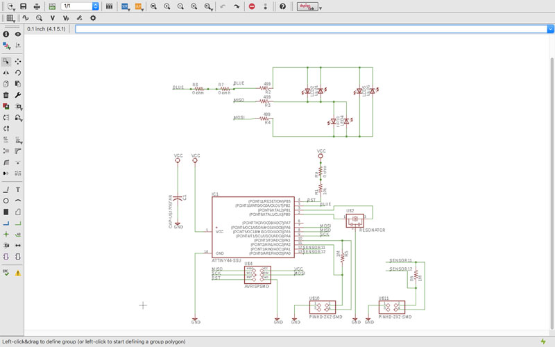 Schematic in Eagle
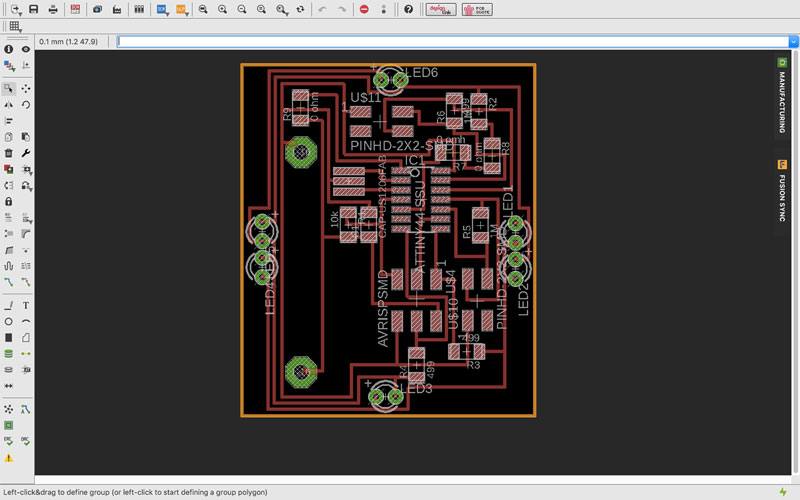 Board design in Eagle
I cut the board using the Roland MDX-20 milling machine, first the traces and then the cutting, just like in previous weeks but this time I also made holes. The holes are part of the cut file, and you have to make sure the holes are bigger than the diameter of your tool.
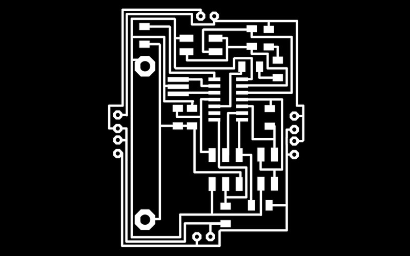 PGN file ready for tracing
 PGN file ready for cutting
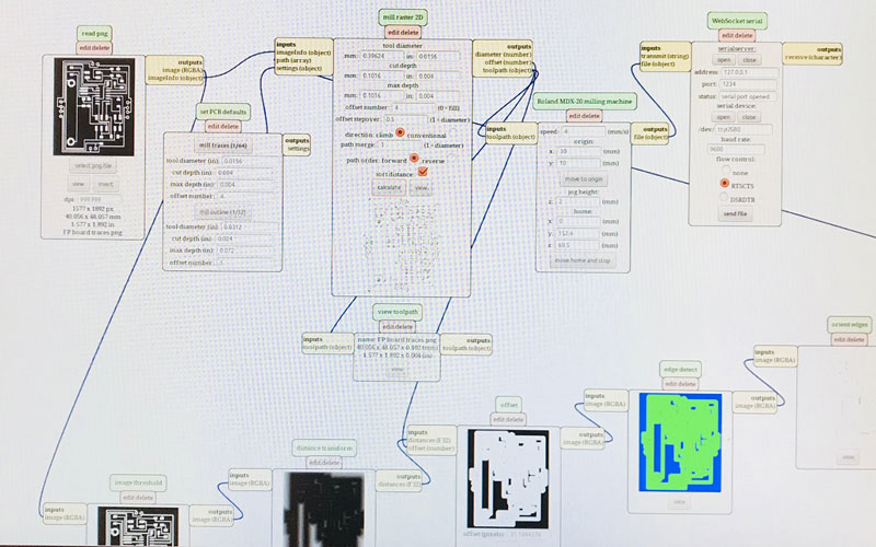 Settings in Mods
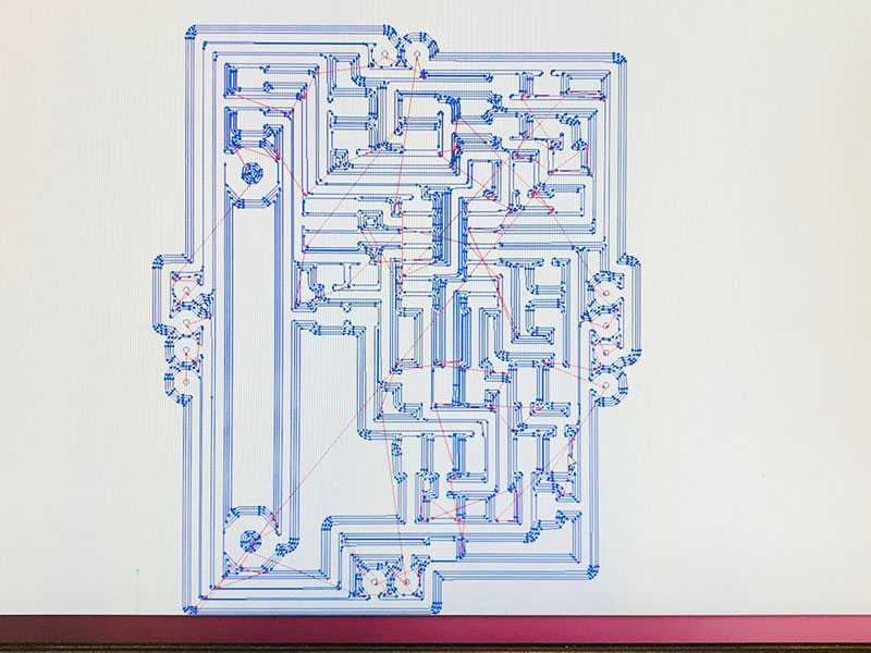 Mods show the traces
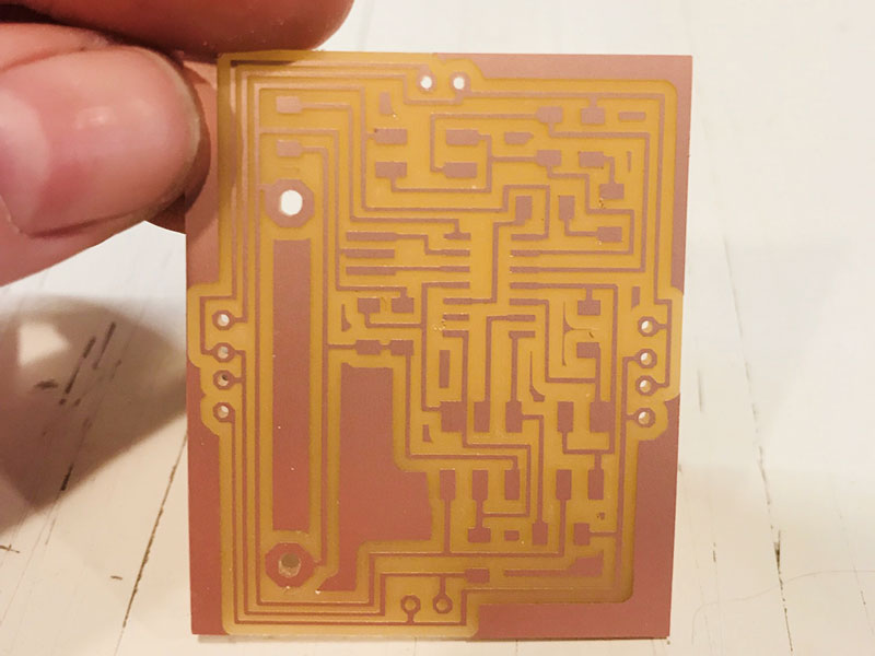 Newly cut board
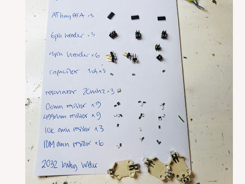 Prior to soldering I made sure I had all components
I soldered on all the pieces to the board, also using wires for the battery holder and the LEDs that will be on the top and the bottom of the cube.
Components on the PCB:
- ATtiny84
- 6 pin header
- 4 pin header x2
- Capacitor 1uf
- Resonator 20 mhz
- Resistor 0 ohm x3
- Resistor 49,9 ohm x3 (Each resistor must have half the value of the required value)
- Resistor 10k ohm x1
- Resistor 10M ohm x2 (With a 10M ohm resistor the sensor will start to respond 10-15cm away)
- 2032 battery holder
- CR2032 Lithium battery 3V
- LED (through hole) 6x
- Wires
- Soldered on to a one-sided copper plate
I make notes to remember the orientation of the board, the anode and cathode of the LEDs, the different pins and which wire should go where.
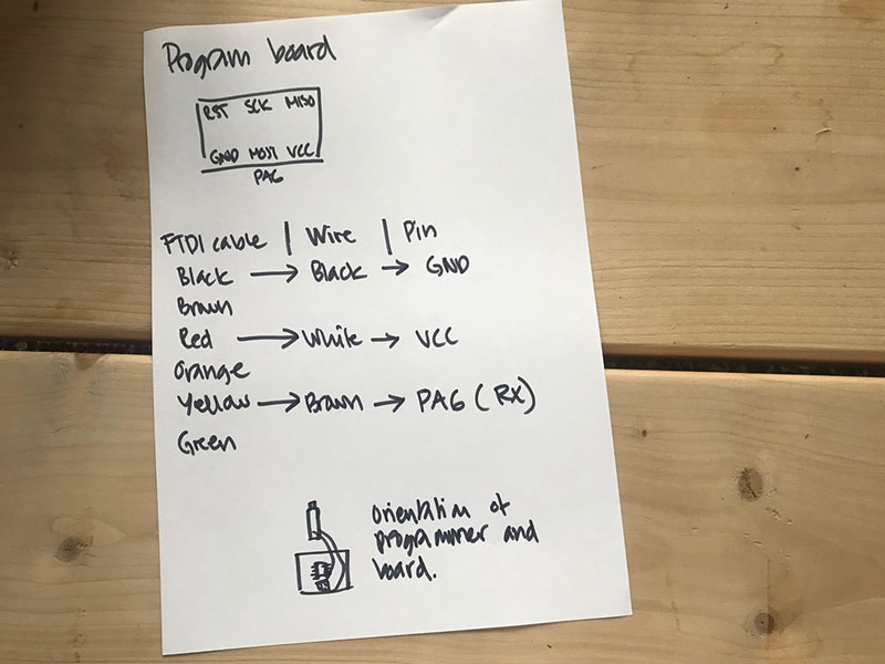 How to connect the cable when programming the board and reading serial
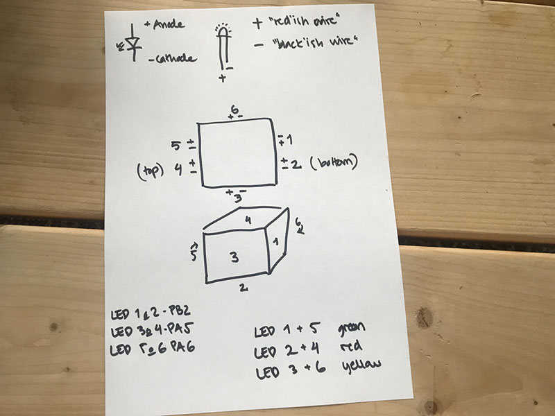 Orientation and placement of LEDs
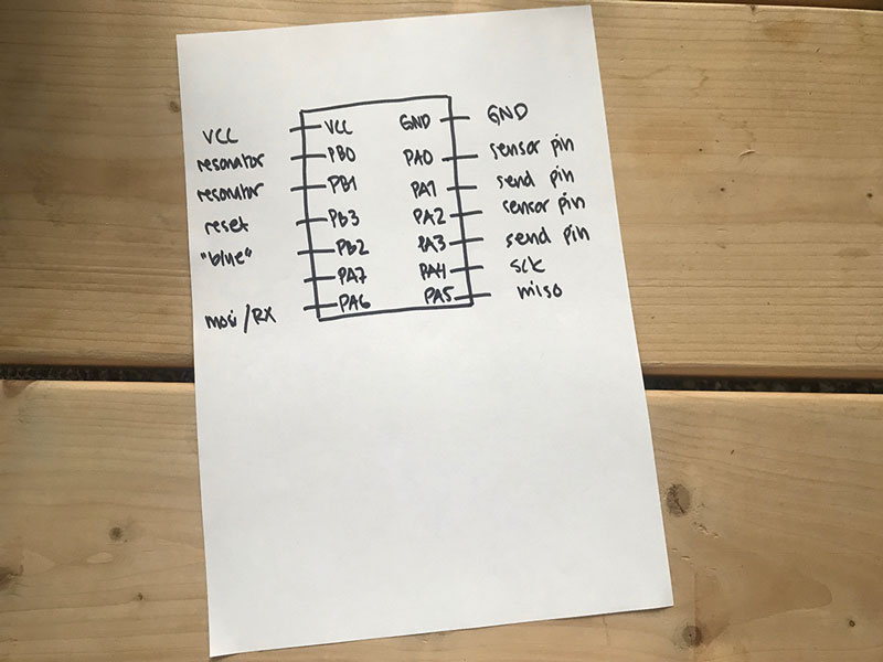 Pin out
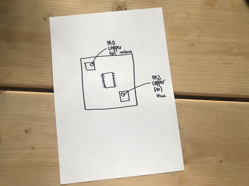 Orientation of sensors
I calculated the value for the resistors connected to the LEDs using Ohm Law; Resistance equals the voltage source minus the voltage drop from the LED divided by the current running through the LED; R=(V SOUCE-V LED)/I LED. It is important to me that the LEDs shine bright, but I also didn't want to burn out the pins that can do a maximum of 20mA. I bought LEDs with a forward voltage of 2V, and I wanted to keep the current through the LED at 10 mA. That gave me a required resistance of 100 ohm. When doing Charlieplexing, two LEDs share one pin, meaning the resistor should be divided in half to supply with the right amount of current.
Future improvements
I like making small and good looking boards. This board is not as small as it can be, and it is not good looking. Since I made some last minute changes to how the battery would be attached and how the LEDs would connect, there is a lot of unused space on the board. Also, since I placed the battery on the back, using wires, I could have put the holes for the battery closer to each other, not taking that much space.
The capacitive sensor can run on one receive pin and multiple send pins. So I could have used fewer pins. Furthermore, since I only have one output, (my initial idea was to have more), I could have been happy with only one sensor.
Inner structure
The main purpose of the inner structure is to hold the PCD board in the middle of the cube, and also to equally spread out the copper foil. One of the main ideas the whole time was that I wanted symmetry; I wanted the LEDs to be placed symmetrically in the cube and shine equally on all sides. Also for the copper foil to be equally spread out on the cube. Furthermore, I had an idea that if I created an inner structure, that one could fit in many different cardboard shapes.
I decided to 3D print my inner structure since it would be hard to do using subractive fabrication. I designed it in Fusion 360 making rectangles that I extruded and cut off the main body. My design of the inner structure makes sure that I can place the PCB board inside it, and also that it can be taken out. I had an idea that I would screw the board on to the inner structure, but I noticed that it wasn’t necessary to hold the board in place.
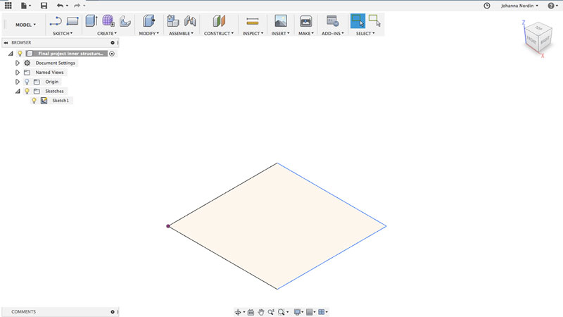 I started of creating a 5x5cm rectangle
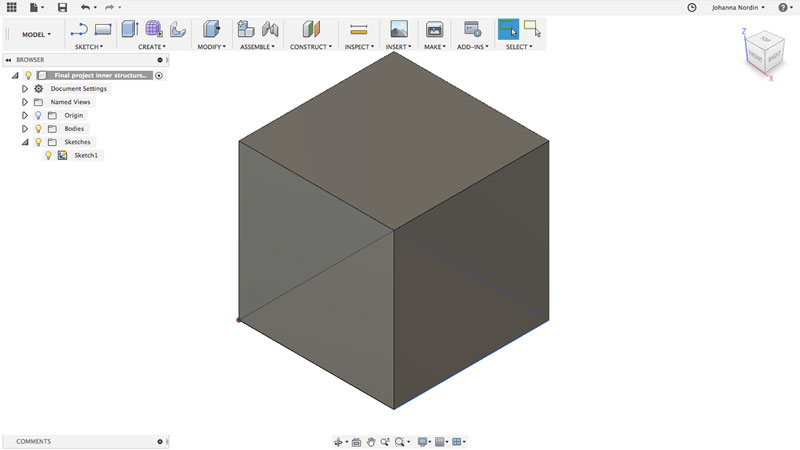 That I extruded
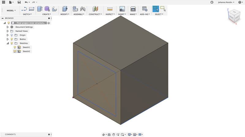 I made a plane on the sides to create a smaller rectangle to extrude to cut a hole
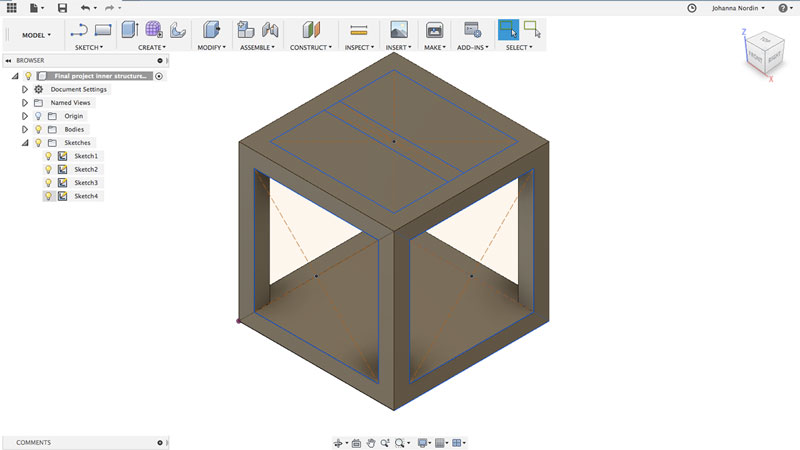 I extruded the holes
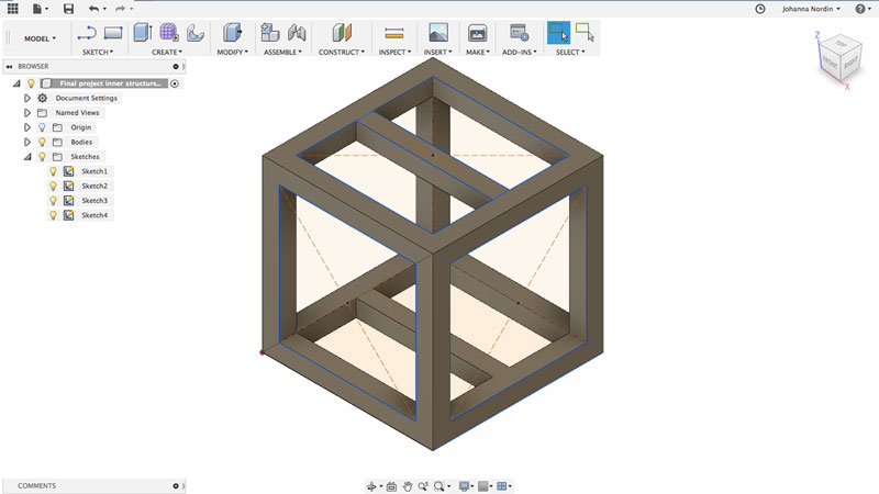 I made two more, smaller rectangles with 5 mm between, extruded them to make the panel for the LEDs
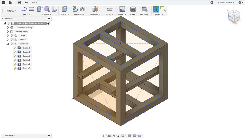 I created the structure for the board to be placed at
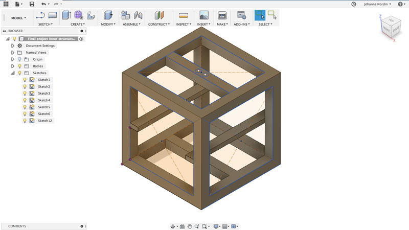 I made holes for the LEDs
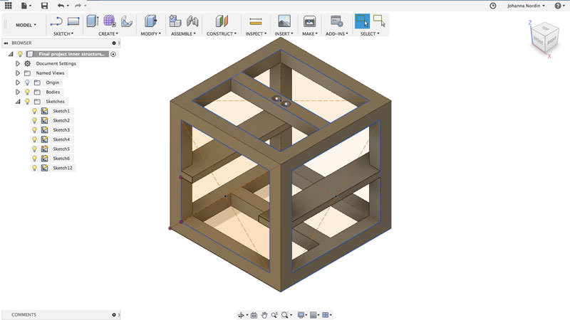 I made the structure widther
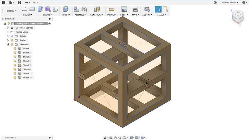 I cut off some of the structure for where the LEDs will be
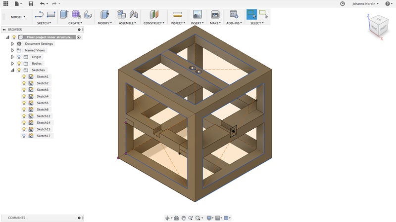 And did the same on the other side and then exported as a STL file
I exported the inner structure as a STL file and imported it into Cura where I decided the settings for the print. The fast print took 3,5 hours, probably because of all the support material, that I decided to go with that and not high quality with thinner layer hight and less speed. I did a prototype which showed that the structure was stable enough.
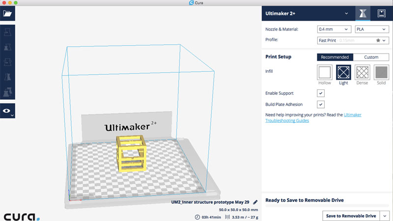 I imported the STL file in Cura
Settings in Cura
- Nozzle: 0.4
- Material: PLA
- Profile: Fast print
- Layer hight: 0,15mm
- Print Speed: 60mm/s
- Travel Speed: 150mm/s
- Shell, Wall Thickness: 0,7mm
- Shell, Top/Bottom Thickness: 0,75mm
- Infill: Light (20%)
- Enable support: Yes
- Build plate adhesion: Yes
The print turned out great, and it was fairly easy to get rid of all the support material. The small holes for the LEDs also turned out well which was my only concern not using high quality print settings.
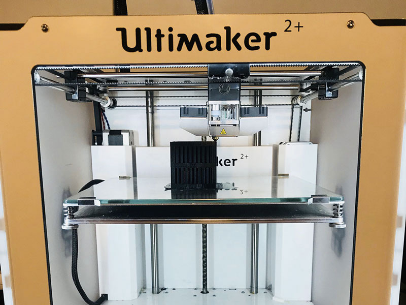 And printed the inner structure with a Ulitmaker 2+
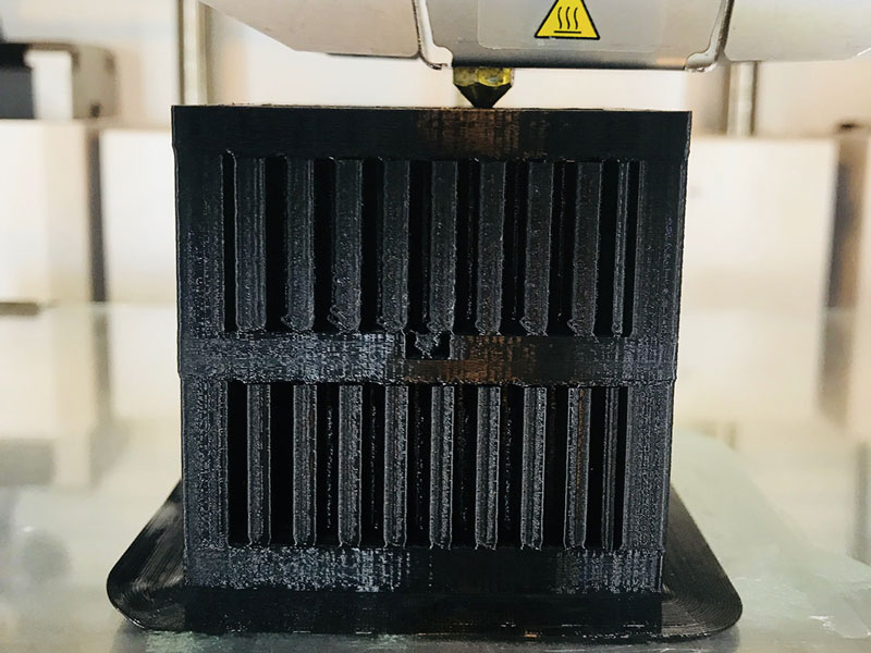 The print went really well
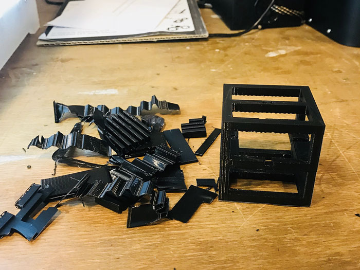 I took away all the extra support material
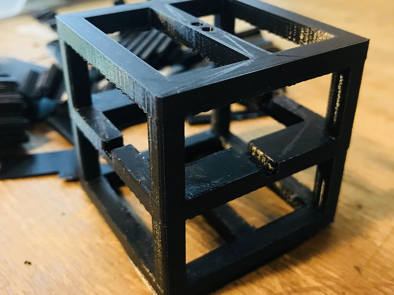 The inner structure printed and done!
Future improvements
If I would have more time, I would re-think how I place the LEDs and how I connect them. The inner structure is so small, that it is very hard to connect the wires to the LEDs. It is also not a very stable solution using wires, but since I wanted to be able to take the cube apart, this was the only option I could think of.
The whole inner stucture could look better and be more user friendly. It is very hard to place the board inside the inner structure and attach all the wires.
The LEDs on top and the bottom does not shine through the cardboard material as well as the ones on the side, which makes my struggle of making the cube symmetrical a bit of a waste.
Cardboard cube
My reason for choosing cardboard as my main material is that it is cheap, easy to modify and prototype with and that it looks very simple; I really like the rough surface. Before deciding on the “stack of cardboard pieces”-design, I was exploring making foldable boxes out of cardboard. However, after seeing this video I decided that I wanted the surprising effect of having the cube look like it doesn’t contain anything, but then it does. I however would have loved it to have more output so that the surprice would be a bit bigger than it is today.
The cardboard cube is 8x8x8 cm, using 3 mm thick cardboard. When prototyping I noticed that the thickness of the cardboard varied, many times it was less than 3 mm, resulting in the cube becoming less than 8 cm high. I changed the thickness of the material in Slicer for Fusion 360 (more about that later), resulting in 29 pieces of cardboard.
The design is made in Fusion 360 and then slicing it in Slicer for Fusion 360. It is a fairly straightforward design comprising of rectangles and circles.
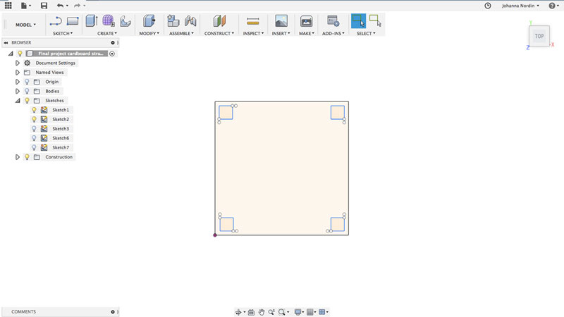 First I made a rectangle with four smaller rectangels for the magnets
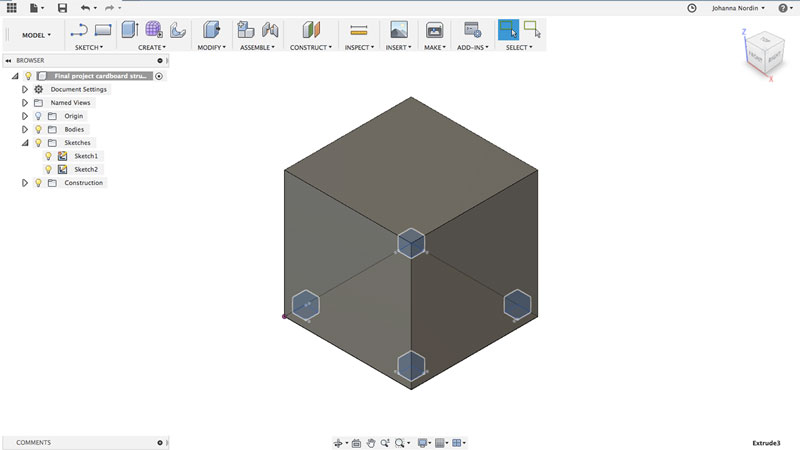 I extruded the big rectangle into a cube and the smaller rectangles I cut of making holes
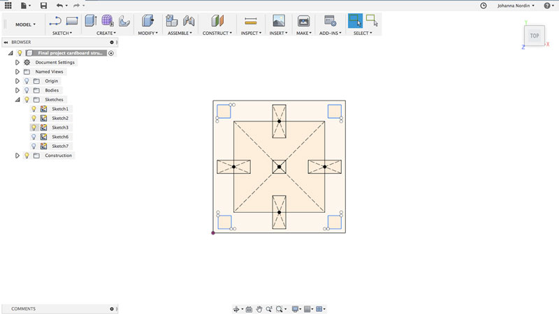 I created rectangles for the inner structure and extra room for the LEDs
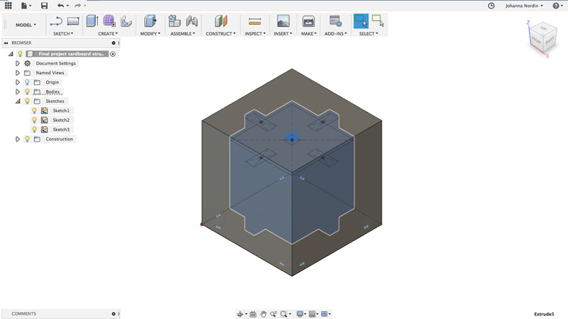 I extruded it and made the cube hollow for the inner structure
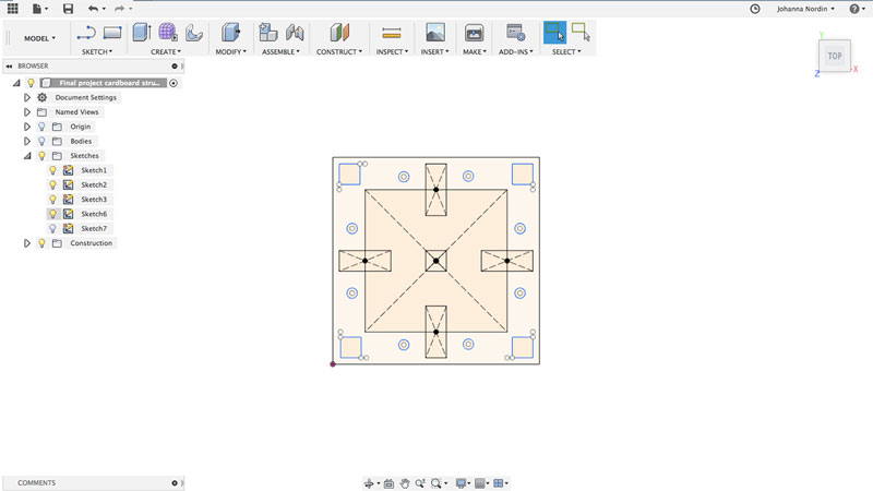 I made circles for the rods
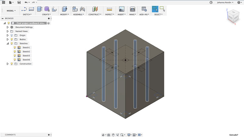 And extruded them almost the whole way through the cube
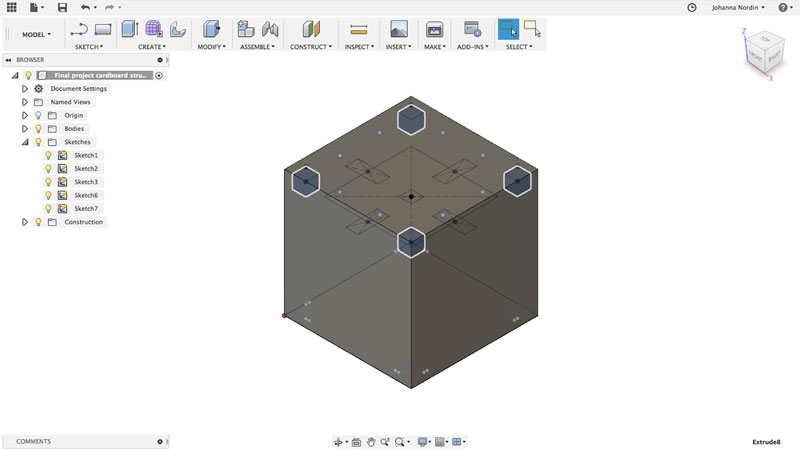 I made four more holes for the magnets
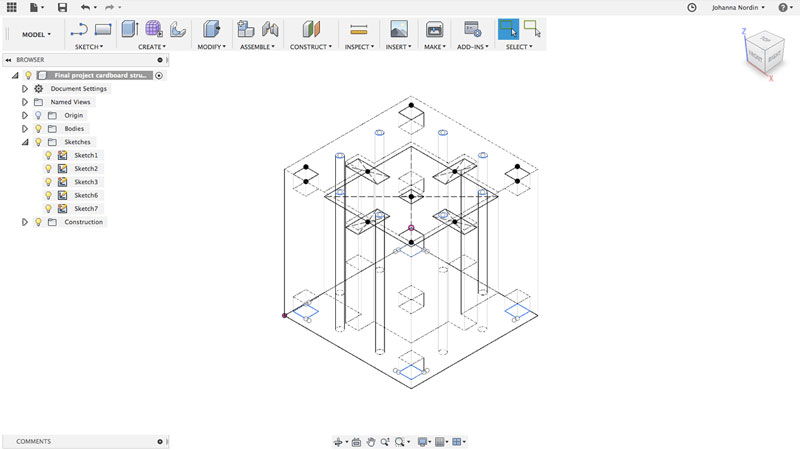 This is how the cube looks beeing transparent
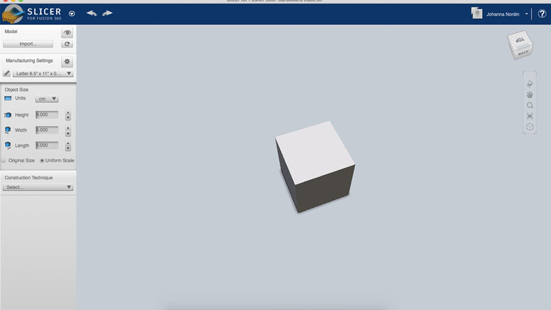 I exported the stl file to Slicer for Fusion 360 and changed the metrics to centimeter
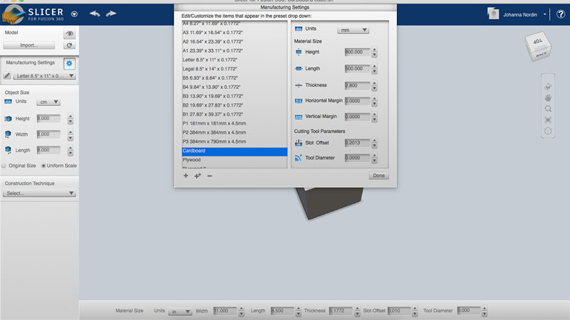 I added a new material, changing the thickness to 2,8mm instead of 3mm
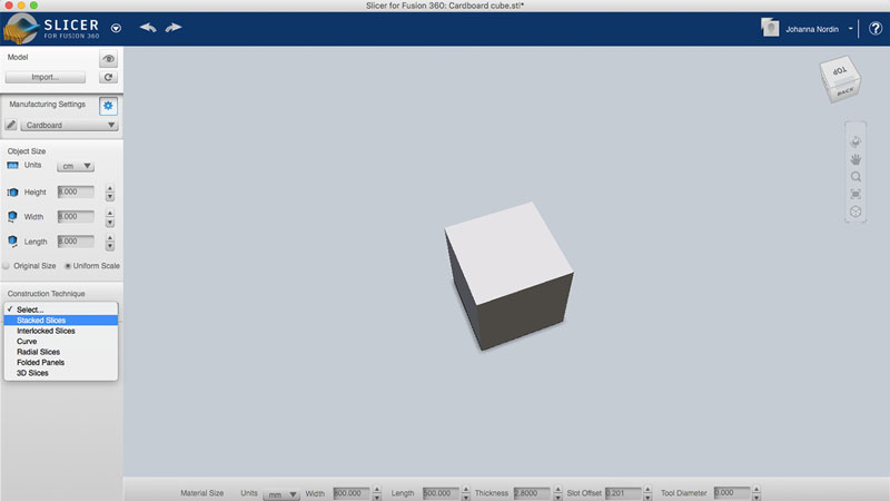 I chose the type of slicer
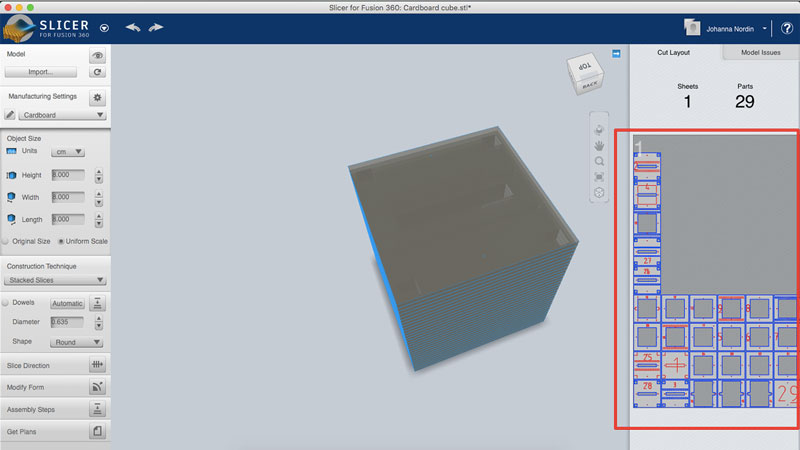 The pieces were the wrong way
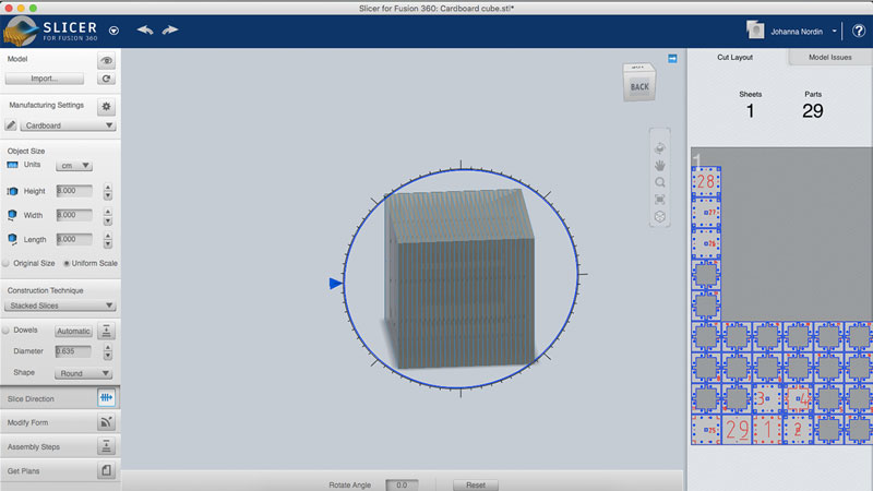 I rotated the cube 90 degrees
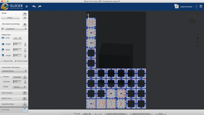 I exported the pieces as a DXF file that can be open in the laser cut software
I uploaded the DXF-file to the laser cut software Lasercut5.3. Slicer for Fusion 360 create numbers for you to keep track of the pieces. Some of them are a bit too big in my opinion. I decided to make them all the same size and put them in the right top corner. I also had to take away the marks Slicers for Fusion 360 create to place the assemble rods. On piece 1 and 29 I created a bigger circle that I cut half way to place the end of the rods, that would hold the pieces together. I marked the pieces that were going to be engraved/cut with less power and spees, and changed the color so I could use a different setting for those pieces.
Settings in Lasercut5.3 for cutting through
- Speed: 150
- Power: 90
Settings in Lasercut5.3 for engraving (still setting "cut")
- Speed: 100
- Power: 15
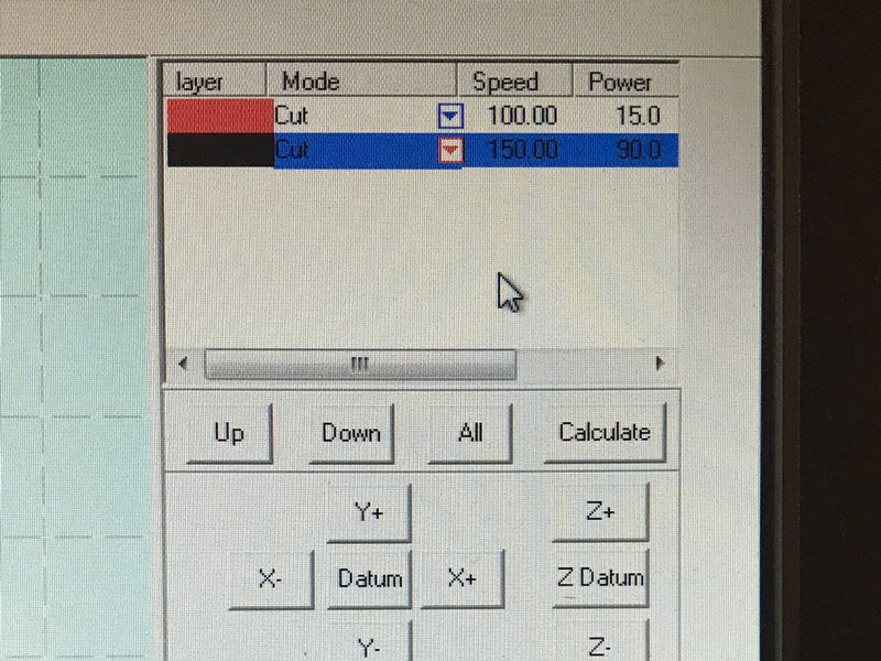 Settings in Lasercut5.3. For engraving the numbers I still use "Cut" but with less power and speed
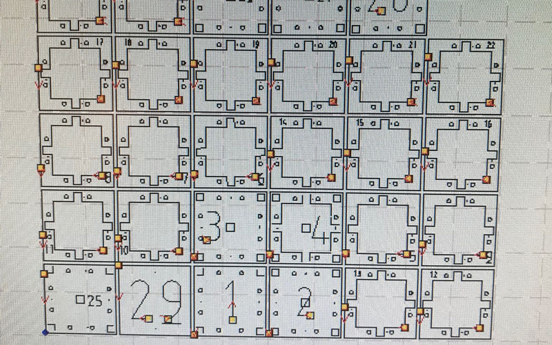 All the pieces in Lasercut5.3. I changed so that all numbers would be in the right top corner
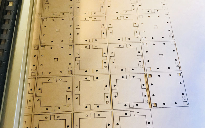 Newly cut pieces
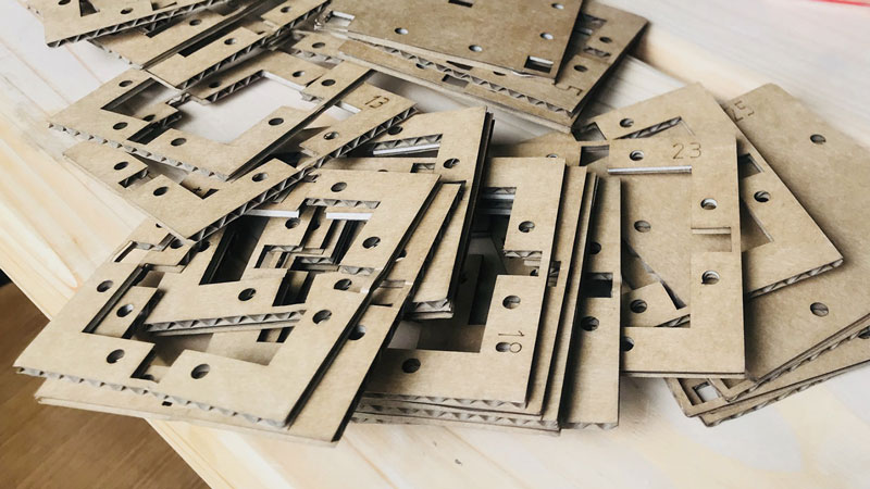 Ready to be assembled!
I assembled the cardboard pieces, varying the rotation of them, making sure that every other had the cardboard “waves” showing. In this way, the LEDs would shine through better than if all pieces were placed that same way.
Future improvements
Some of the middle parts that have a lot of material cut off are a bit unstable and can fold if you press them too hard. I wanted to keep the cube as small as possible, but I could have added some millimeters to avoid this unstableness.
The design could be more than just rectangels and circles, making it look a bit more interesting.
I decided very late how I wanted to keep the pieces together. This resulted in me only using four out of the eight holes that I made for the rods. I could just take four of the holes away, but to keep the symmentry I would have wanted to redesign the whole cube then. Also, I didn't want to show anything else but cardboard on the outside of the cube. Using the rods in this way, one can see them from the outside, which I don't like.
I didn’t make any more shapes than just a cube. It would be fun to make a sphere.
Copper foil
For the sensors to work, they need to be connected to copper foil. Since I have two sensors I needed two different copper foils to be connected. By creating a design covering three sides of the cube, the two sensor would have one copper foil each. Instead of cutting the copper foil by hand, I vinyl cut it. I wanted it to fit the inner structure perfectly. I made the design in Illustrator, just drawing lines with the right distans, measuring the inner structure. I first made the foil as big as the inner structure; each "pillar" being 5 mm wide, but since that could cause that the two capacitors to connect, I made the copper foil 1 mm thinner.
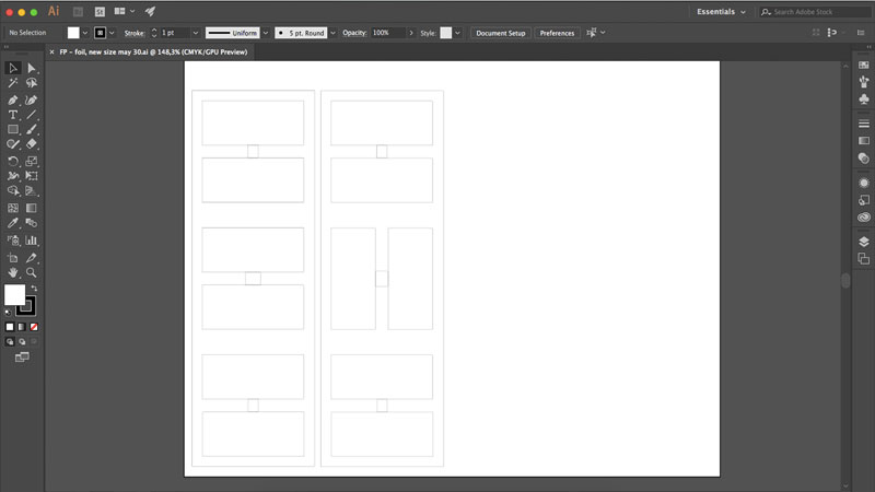 Copper foil design in Illustrator
The menu in this machine is not really user friendly, it’s hard to know where to go and why. But by clicking around I got to pick if I was using a role or a piece of vinyl. Furthermore, I set the origin of the blade; pressing "origin" till it flashes on the display. I set the "blade force" to 100 gf and "speed" to 5 cm/second, and I did a test. The test is done by pressing "test" for 0.5 seconds or more. The test went fine.
- Force: 100gf
- Speed: 5cm/s
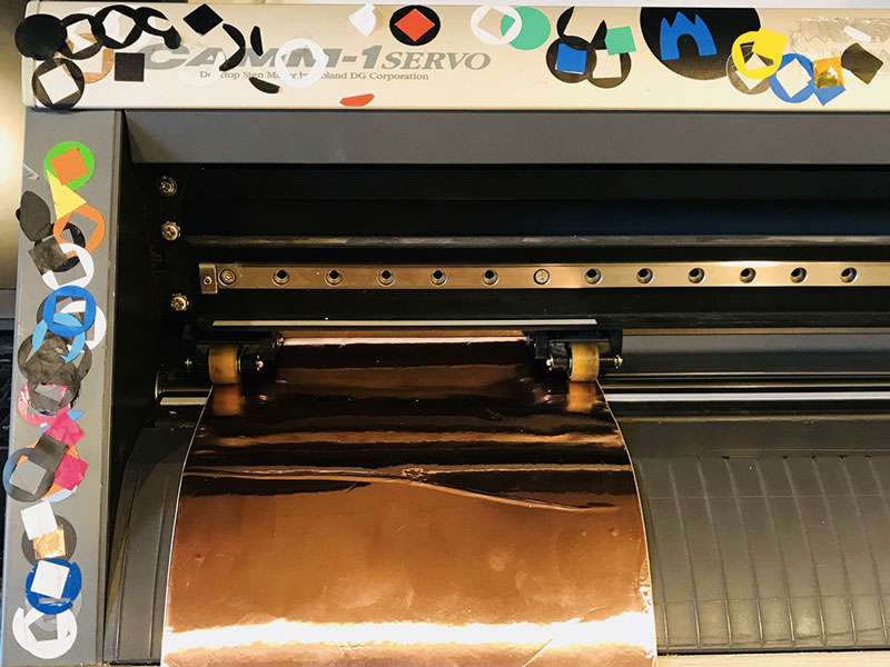 Place the roll in the vinyl cutter Roland
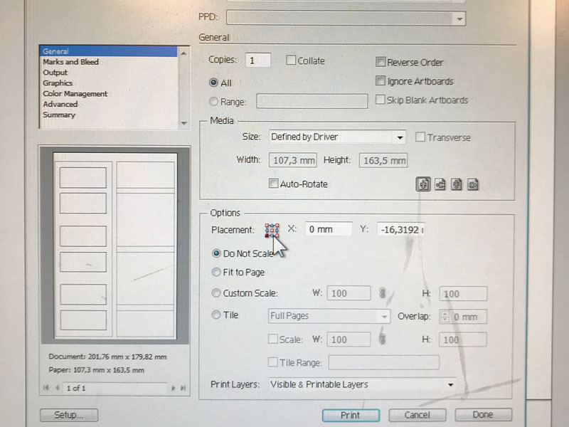 Print settings, placement
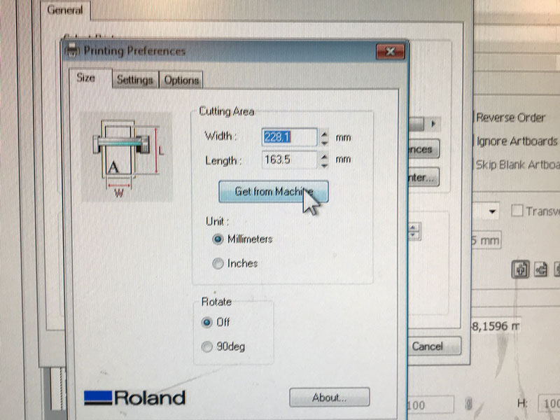 Print settings, size
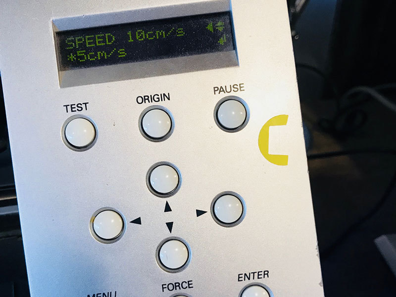 Speed: 10cm/s
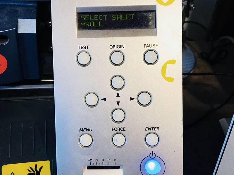 Select roll
The cut went fine and I could take away the extra material and place the copper foil on the inner structure.
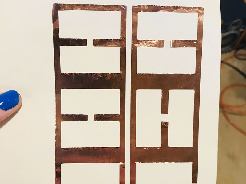 Cut and extra material taken off
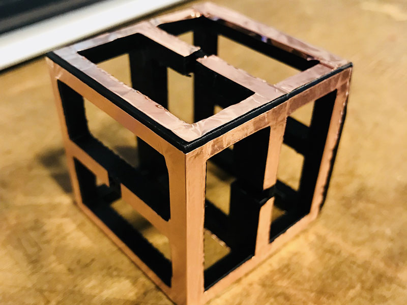 Placed on inner structure
Future improvements
I am fairly happy with the result of the copper foil. The cut when well, however when I attached it to the inner structure, some bubbles were created and the foil got to look at bit more messy than needed.
Rods
The initial idea was not to make rods like these ones to attach the cardboard pieces together. I didn't want the outside of the cube to show anything else but the cardboard, making the surprise bigger. Due to time limitations, this was the best option I could think of, not using glue or screws.
I made the design i Fusion 360, making three different sizes of circles that I extruded different lengths.
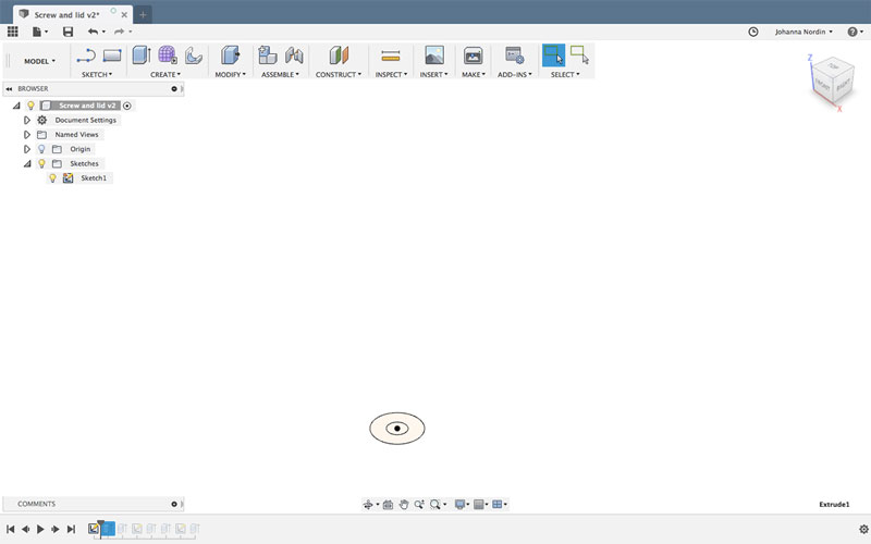 First two circles
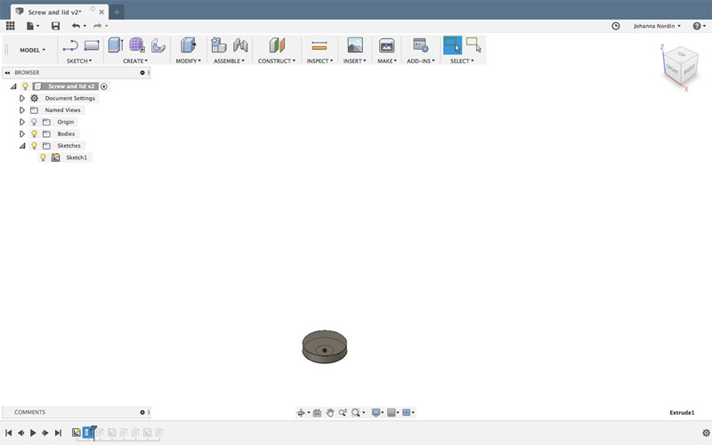 Extrude the first one
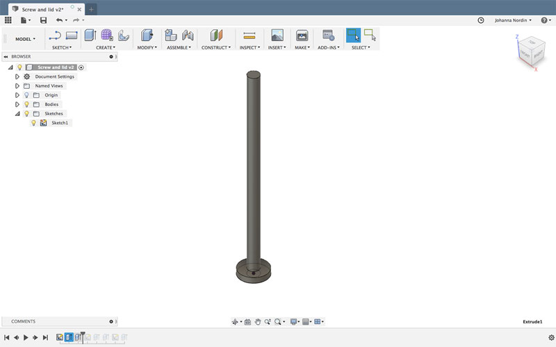 Extrude the second one
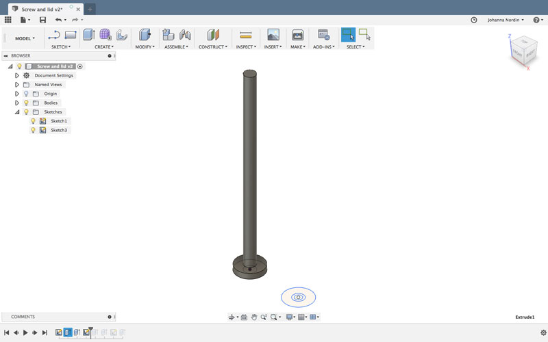 Create two new circles for the cap
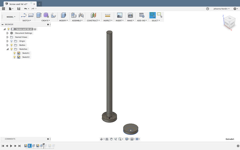 Extrude the first
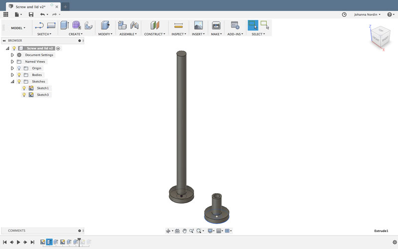 Extrude the second
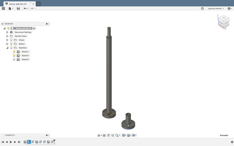 Create new circle and extrude for the part that goes into the cap
I exported the rods and the cap as two different STL files. I imported them into Cura and changed the settings to High quality, since the rods is so fragile and small.
- Nozzle: 0.4
- Material: PLA
- Profile: High quality
- Layer hight: 0,06mm
- Print Speed: 50mm/s
- Travel Speed: 120mm/s
- Shell, Wall Thickness: 1,05mm
- Shell, Top/Bottom Thickness: 0,72mm
- Infill: 100%
- Enable support: No
- Build plate adhesion: Yes
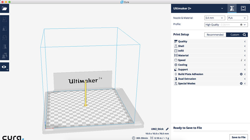 Rods imported in Cura
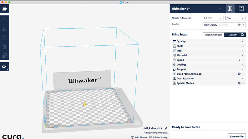 Cap inported in Cura
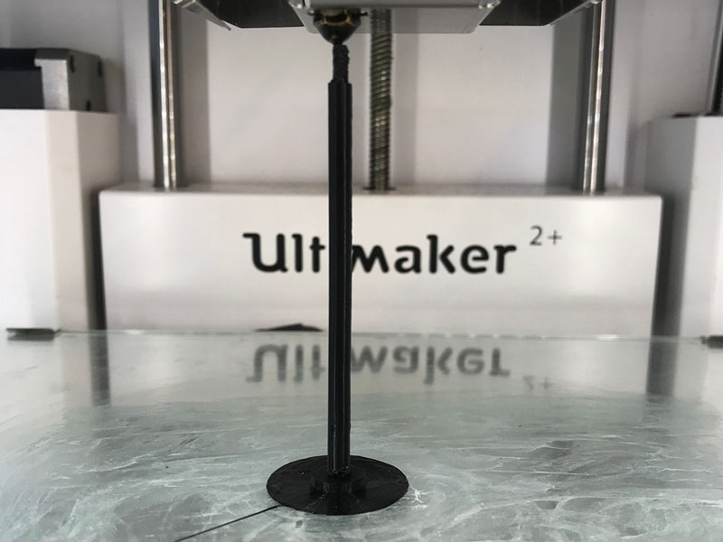 The rods almost done
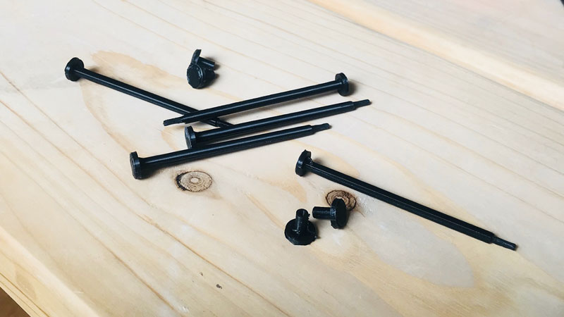 Rods and caps finished!
Future improvements
The rods are fine as a solution for now. I will try to think of other ways to assemble the pieces together.
Code
I used Arduino IDE to code my board. The code that I am using for this project is a combination of code on Charlieplexing and capacitive sensors. I tried both seperatly before adding them together to make sure that the board was working fine. I also added code to use the serial monitor in Arduino IDE to calibrate the sensors and have an understanding of what was happening.
First I had to install the library for the capacitive sensor. To add capacitiveSensor to a new sketch I choose Sketch->Import Library->CapacitiveSensor. I also added the library for using the serial monitor. I set all the pins; the pins for the serial monitor, (the tx pin could be the same as the LED pin since it will only be used when calibrating the sensors), the send and receive pins for the two sensors, and the LEDs. I also defines´d the software serial and the two sensors. All this before the void setup.
Note that I will have to take away the symbol, the opposite to > when writing here, since Dreamweaver thinks that I'm wirting HTML. For the full code, see downloadable file
#include CapacitiveSensor.h> //add library for capacitive sensing
#include SoftwareSerial.h> //add library for serial monitor
int rxPin = PA7; //rx is pin PA7
int txPin = PA6; //tx is pin PA6
int receive_pin = PA0; //receive pin for sensor CS_top01 (sensor pin)
int send_pin = PA1; //send pin for sensor CS_top01
int receive_pin2 = PA2; //receive pin for sensor CS_bottom23 (sensor pin)
int send_pin2 = PA3; //send pin for sensor CS_bottom23

const int LED_1 = 8; //LED on PB2
const int LED_2 = A5; // LED on PA5
const int LED_3 = A6; // LED on PA6


SoftwareSerial serial(rxPin, txPin); //define SoftwareSerial

CapacitiveSensor   CS_top01 = CapacitiveSensor(send_pin,receive_pin); //define CapacitiveSensor för top sensor
CapacitiveSensor   CS_bottom23 = CapacitiveSensor(send_pin2,receive_pin2); //define CapacitiveSensor for bottom sensor
In void setup, there is no need to set anything for the Charlieplexing. The only code I wrote there is the different pin modes for rx and tx, and the sensors. The autocalibration for the sensors are also set in void setup.
void setup(){
  pinMode(rxPin, INPUT); //set pin mode för rx to input
  pinMode(txPin, OUTPUT); //set pin mode för tx to output
  serial.begin(9600); //initiate serial

  pinMode(receive_pin, INPUT); //set pin mode for the receive pin to input
  pinMode(send_pin, OUTPUT); //set pin mode for the send pin to output

  pinMode(receive_pin2, INPUT); //set pin mode for the receive pin to input
  pinMode(send_pin2, OUTPUT); //set pin mode for the send pin to output

  CS_top01.set_CS_AutocaL_Millis(0xFFFFFFFF); //turn off autocalibrate on top sensor
  CS_bottom23.set_CS_AutocaL_Millis(0xFFFFFFFF); // turn off autocalibrate on bottom sensor

  }
In void loop, all the code for the "if, else" for the LED are set. But before that I added the code for how to calculate the sensor values, using millis to count the milliseconds from the send pin to the receive pin.
void loop(){
  long start1 = millis(); //millis = returns the number of ms since program started
  long start2 = millis(); //millis = returns the number of ms since program started
  long total1 =  CS_top01.capacitiveSensor(30); //number of times the sensor measure
  long total2 =  CS_bottom23.capacitiveSensor(30);//number of times the sensor measure
The "if, else" code for the LEDs have them do different things depending on the sensor value from one or both sensors. "if(total1 > xx || total2 > xx)" means that if either total1 or total2 is greater than xx, then the statement. "if(total1 > xx && total2 > xx)" means that if both total1 and total2 is greater than xx, then the statement.
if(total1 > 1000 == total2 > 1000){ //if both total is higher than
        //blink all LEDs
        //turn on LED 1
        pinMode(LED_1, OUTPUT); //row 1
        digitalWrite(LED_1, LOW);
        pinMode(LED_2, OUTPUT); //row 2
        digitalWrite(LED_2, HIGH);
        pinMode(LED_3, INPUT); //row 3
        digitalWrite(LED_3, LOW);

        delay(100);

        //turn on LED L2
        pinMode(LED_1, OUTPUT); //row 1
        digitalWrite(LED_1, HIGH);
        pinMode(LED_2, OUTPUT); //row 2
        digitalWrite(LED_2, LOW);
        pinMode(LED_3, INPUT); //row 3
        digitalWrite(LED_3, LOW);

        delay(100);

        //turn on LED L3
        pinMode(LED_1, INPUT); //row 1
        digitalWrite(LED_1, LOW);
        pinMode(LED_2, OUTPUT); //row 2
        digitalWrite(LED_2, HIGH);
        pinMode(LED_3, OUTPUT); //row 3
        digitalWrite(LED_3, LOW);

        delay(100);

        //turn on LED L4
        pinMode(LED_1, INPUT); //row 1
        digitalWrite(LED_1, LOW);
        pinMode(LED_2, OUTPUT); //row 2
        digitalWrite(LED_2, LOW);
        pinMode(LED_3, OUTPUT); //row 3
        digitalWrite(LED_3, HIGH);

        delay(100);

        //turn on LED L5
        pinMode(LED_1, OUTPUT);
        digitalWrite(LED_1, HIGH);
        pinMode(LED_2, INPUT);
        digitalWrite(LED_2, LOW);
        pinMode(LED_3, OUTPUT);
        digitalWrite(LED_3, LOW);

        delay(100);

        //turn on LED L6
        pinMode(LED_1, OUTPUT); //row 1
        digitalWrite(LED_1, LOW);
        pinMode(LED_2, INPUT); //row 2
        digitalWrite(LED_2, LOW);
        pinMode(LED_3, OUTPUT); //row3
        digitalWrite(LED_3, HIGH);

        delay(100);
        }

  else if (total1 > 1000 || total2 > 1000){ //if either 1 or 2 is higher than
        //blink red
        //turn on LED L2
        pinMode(LED_1, OUTPUT); //row 1
        digitalWrite(LED_1, HIGH);
        pinMode(LED_2, OUTPUT); //row 2
        digitalWrite(LED_2, LOW);
        pinMode(LED_3, INPUT); //row 3
        digitalWrite(LED_3, LOW);

        delay(10);

        //turn on LED L4
        pinMode(LED_1, INPUT); //row 1
        digitalWrite(LED_1, LOW);
        pinMode(LED_2, OUTPUT); //row 2
        digitalWrite(LED_2, LOW);
        pinMode(LED_3, OUTPUT); //row 3
        digitalWrite(LED_3, HIGH);

        delay(10);

        }
  else if (total1 > 500 || total2 > 500){ //if either 1 or 2 is higher than
        //blink green
        //turn on LED L1
        pinMode(LED_1, OUTPUT); //row 1
        digitalWrite(LED_1, LOW);
        pinMode(LED_2, OUTPUT); //row 2
        digitalWrite(LED_2, HIGH);
        pinMode(LED_3, INPUT); //row 3
        digitalWrite(LED_3, LOW);

        delay(10);

        //turn on LED L5
        pinMode(LED_1, OUTPUT);
        digitalWrite(LED_1, HIGH);
        pinMode(LED_2, INPUT);
        digitalWrite(LED_2, LOW);
        pinMode(LED_3, OUTPUT);
        digitalWrite(LED_3, LOW);

        delay(10);

        }

  else if (total1 > 200 || total2 > 200){ //if either 1 or 2 is higher than
        //blink yellow
        //turn on LED L3
        pinMode(LED_1, INPUT); //row 1
        digitalWrite(LED_1, LOW);
        pinMode(LED_2, OUTPUT); //row 2
        digitalWrite(LED_2, HIGH);
        pinMode(LED_3, OUTPUT); //row 3
        digitalWrite(LED_3, LOW);

        delay(10);

        //turn on LED L6
        pinMode(LED_1, OUTPUT); //row 1
        digitalWrite(LED_1, LOW);
        pinMode(LED_2, INPUT); //row 2
        digitalWrite(LED_2, LOW);
        pinMode(LED_3, OUTPUT); //row3
        digitalWrite(LED_3, HIGH);

        delay(10);

        }
  else{

      }
I end all the code with the serial print to have an understanding of what is going on with the sensors.
serial.print("Top sensor:");
serial.print(millis() - start1); //check on performance in ms
serial.print("\t"); //tab character for debug window spacing
serial.print(total1); //print output from top sensor
serial.println("\t");

serial.print("Bot sensor:");
serial.print(millis() - start2); //check on performance in ms
serial.print("\t"); //tab character for debug window spacing
serial.print(total2); //print output from bottom sensor
serial.println("\t");

delay(100); //delay to limit data to serial port
}
Bill of materials
All my components and material can be found in the Fab Lab. Fab Lab buys them from electronic resellers in China or from Digi-Key. The magnets and the battery makes up more than half the cost of the cube. The components and the material all cost less if you buy more than just one, making these costs at the highest level.
Cost per cube:
- Cardboard: € 0,98 (4,90 for a piece fitting 5 cubes)
- PLA: about € 1,00
- Cube Magnets: € 3.04 (0.38 €/magnet)
- Copper foil: about € 0,50
- Components:
- ATtiny84: € 0,58
- 6 pin header: € 0,24
- 4 pin header x2: € 0,14
- Capacitor 1uf: € 0,28
- Resonator 20mhz: € 0,33
- Resistor 0 ohm 3x: € 0,33
- Resistor 49,9 ohm x3: € 0,30 (might change)
- Resistor 10k ohm x1: € 0,10
- Resistor 10M ohm x2: € 0,20
- 2032 battery holder: € 0,56
- CR2032 Lithium battery 3V: 2,95 €
- LED (through hole) 6x: 0,75 €
- Wires: € 0,1
- One-sided copper plate: € 0,5
- Total: around 12 €
Licence
Even though I'm not planning to claim any rights or licensing my final project, I did find one licens that I liked and could use another time. On Creative Commons website you can read about how they help to legally share knowledge and creativity. They do this to build a more equitable, accessible, and innovative world which is inline with my values. Creative Commons offer free, easy-to-use copyright licenses. They provide a simple, standardized way to give permission to share and use creative work.
The license I would use is the "Attribution 4.0 International" which they recommend when going through their website and selecting the options you would like for your license. The license says "You are free to: Share — copy and redistribute the material in any medium or format. Adapt — remix, transform, and build upon the material for any purpose, even commercially. This license is acceptable for Free Cultural Works. The licensor cannot revoke these freedoms as long as you follow the license terms." It continues "Under the following terms:Attribution — You must give appropriate credit, provide a link to the license, and indicate if changes were made. You may do so in any reasonable manner, but not in any way that suggests the licensor endorses you or your use. No additional restrictions — You may not apply legal terms or technological measures that legally restrict others from doing anything the license permits."
Download files here
Board design (schematic)
Board design (board)
Board design (trace file)
Board design (cut file)
Cardboard cube stl
Cardboard cube in Slicer for Fusion 360 eps
Cardboard cube in Slicer for Fusion 360 dxf
Cardboard cube in Slicer for Fusion 360 3dmk
Cardboard cube files from laser cutter
Copper foil ai
Inner structure stl
Rods slt
Caps to rods slt
Code
The process:
first week of planning and sketching a potential final project
January, 2018A toy for kids
My initial idea for my final project is to create a toy for kids, to learn from, and interact with. A goal of mine is to start a preschool in Sweden at some point, and I would like to make a toy that could be used there, and elsewhere. I want kids to explore and learn from experiences. I want kids to not just be consumers of technology, but also producers.
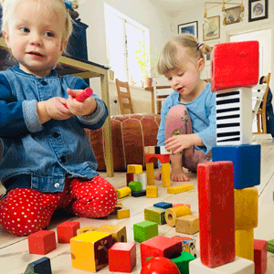
Ingrid the Tiger and Ebbe the Bear
Interactive building blocks
The toy would look like a typical wooden building block, a cube. I know from playing with my sister’s kids; Ingrid the Tiger and Ebbe the Bear, four and soon to be two years old, that they really like playing with these old-school wooden blocks. I will add some features to these blocks, since I also know that the Bear loves music and the Tiger loves stuff that is lit up. I’m not sure just yet what the different features will we, maybe some sound, some light and maybe some movement or vibration, that I will figure out later.
The idea is that if you put two or more blocks together, one or several features will be activated. My initial idea is that the two opposite sides of the block will have the same feature, let’s say sound. If you put two blocks together, with the sound side towards each other, a sound will play. However, if you put a sound and a light side together, nothing would happen.
I’m in the process of exploring what would happen if you put three or more blocks together, if that would create a sequence of light, music, movement, or what would happen.
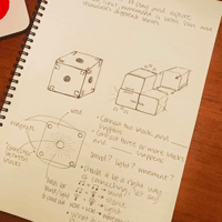 My notes
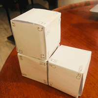 Paper prototype
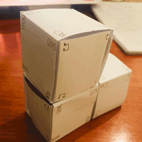 Paper prototype
Who is it for?
This toy is for all kids, mostly targeting kids around the age of two to four, that like to build things and explore possibilities. The toy could possibly enhance the kid’s logical thinking and stimulate their different senses. The explicit advantages of this toy are still to be discovered.
Material
I want the main material to be some type of wood. I believe it's a fun material to work with. It looks nice too and it's many times a better material for kids compared for example plastic. I don't know yet what components I will use, most certainly some type of battery, electronic connector and some magnets or similar to connect the blocks to one another.
Inspiration
I got inspired by my local instructor Emma Pareschi’s final project from back in 2014. I especially like how she integrated the electronics into the wood and the small holes she made for the light.
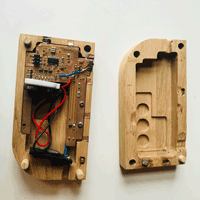 The electronics in nicely integrated into the wood
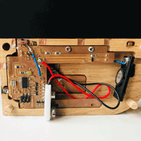 The electronics
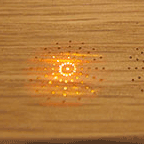 The wholes for the light
I also got to see a project from some time back when the blocks were connected using magnets and with a thing (a name I don’t know yet) that connected the electronics between the blocks.
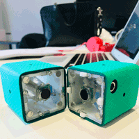 Magnets to connect, electronic connector in the middle
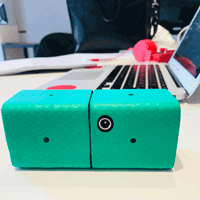 Connected
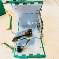 The inside
The process:
first prototype of new idea
May, 2018Design and make a test board
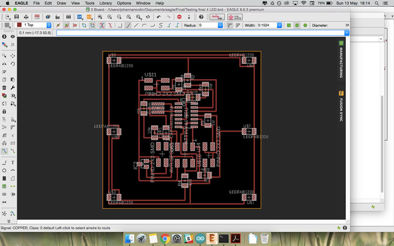 Design the test board
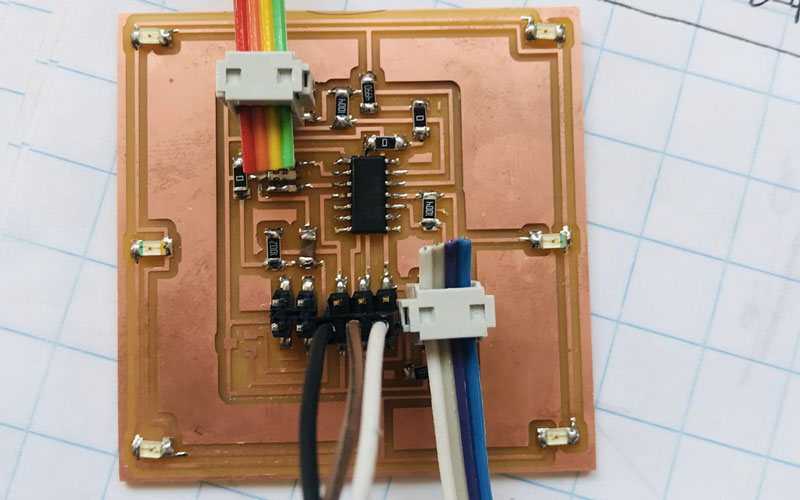 The board
Testing the board
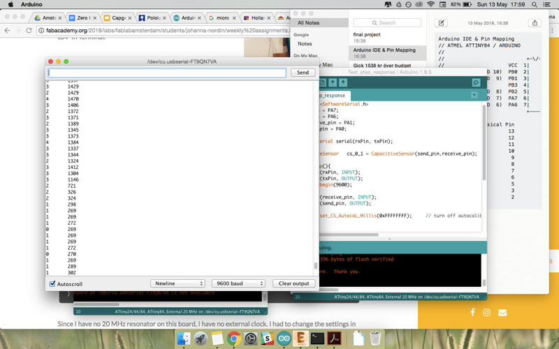 Testing the step response
Testing the Charlieplexing
The code is from Xavier's output week
//Setting the pin for each row.
const int LED_1 = 8; //LED row 1
const int LED_2 = A5; //LED row 2
const int LED_3 = A6; //LED row 3

//Nothing in void setup()
void setup()
{
}

void loop()
{

//So for each LED, there's differents way to set the pins (Output or Input, Low or High)
//turn on LED 1
pinMode(LED_1, OUTPUT); //row 1
digitalWrite(LED_1, LOW);
pinMode(LED_2, OUTPUT); //row 2
digitalWrite(LED_2, HIGH);
pinMode(LED_3, INPUT); //row 3
digitalWrite(LED_3, LOW);

delay(100);

//turn on LED L2
pinMode(LED_1, INPUT); //row 1
digitalWrite(LED_1, LOW);
pinMode(LED_2, OUTPUT); //row 2
digitalWrite(LED_2, LOW);
pinMode(LED_3, OUTPUT); //row 3
digitalWrite(LED_3, HIGH);

delay(100);

//turn on LED L3
pinMode(LED_1, OUTPUT); //row 1
digitalWrite(LED_1, HIGH);
pinMode(LED_2, OUTPUT); //row 2
digitalWrite(LED_2, LOW);
pinMode(LED_3, INPUT); //row 3
digitalWrite(LED_3, LOW);

delay(100);

//turn on LED L4
pinMode(LED_1, INPUT); //row 1
digitalWrite(LED_1, LOW);
pinMode(LED_2, OUTPUT); //row 2
digitalWrite(LED_2, HIGH);
pinMode(LED_3, OUTPUT); //row 3
digitalWrite(LED_3, LOW);

delay(100);

//turn on LED L5
pinMode(LED_1, OUTPUT); //row 1
digitalWrite(LED_1, LOW);
pinMode(LED_2, INPUT); //row 2
digitalWrite(LED_2, LOW);
pinMode(LED_3, OUTPUT); //row3
digitalWrite(LED_3, HIGH);

delay(100);

//turn on LED L6
pinMode(LED_1, OUTPUT);
digitalWrite(LED_1, HIGH);
pinMode(LED_2, INPUT);
digitalWrite(LED_2, LOW);
pinMode(LED_3, OUTPUT);
digitalWrite(LED_3, LOW);

delay(100);

//turn on LED L5
pinMode(LED_1, OUTPUT); //row 1
digitalWrite(LED_1, LOW);
pinMode(LED_2, INPUT); //row 2
digitalWrite(LED_2, LOW);
pinMode(LED_3, OUTPUT); //row3
digitalWrite(LED_3, HIGH);

delay(100);

//turn on LED L4
pinMode(LED_1, INPUT); //row 1
digitalWrite(LED_1, LOW);
pinMode(LED_2, OUTPUT); //row 2
digitalWrite(LED_2, HIGH);
pinMode(LED_3, OUTPUT); //row 3
digitalWrite(LED_3, LOW);

delay(100);

//turn on LED L3
pinMode(LED_1, OUTPUT); //row 1
digitalWrite(LED_1, HIGH);
pinMode(LED_2, OUTPUT); //row 2
digitalWrite(LED_2, LOW);
pinMode(LED_3, INPUT); //row 3
digitalWrite(LED_3, LOW);

delay(100);

//turn on LED L2
pinMode(LED_1, INPUT); //row 1
digitalWrite(LED_1, LOW);
pinMode(LED_2, OUTPUT); //row 2
digitalWrite(LED_2, LOW);
pinMode(LED_3, OUTPUT); //row 3
digitalWrite(LED_3, HIGH);

delay(100);

}
Testing the step response
#include CapacitiveSensor.h>
#include SoftwareSerial.h>
int rxPin = PA7;
int txPin = PA6;
int receive_pin = PA1;
int send_pin = PA0;

SoftwareSerial serial(rxPin, txPin);

CapacitiveSensor   cs_0_1 = CapacitiveSensor(send_pin,receive_pin);        // 10 megohm resistor between pins 4 & 2, pin 2 is sensor pin, add wire, foil

void setup(){
  pinMode(rxPin, INPUT);
  pinMode(txPin, OUTPUT);
  serial.begin(9600);

  pinMode(receive_pin, INPUT);
  pinMode(send_pin, OUTPUT);

  cs_0_1.set_CS_AutocaL_Millis(0xFFFFFFFF);     // turn off autocalibrate on channel 1 - just as an example


}

void loop(){
    long start = millis();
    long total1 =  cs_0_1.capacitiveSensor(30);

    serial.print(millis() - start);        // check on performance in milliseconds
    serial.print("\t");                    // tab character for debug window spacing

    serial.print(total1);                  // print sensor output 1
    serial.println("\t");
    delay(10);                             // arbitrary delay to limit data to serial port
}
Design and make a inner structure
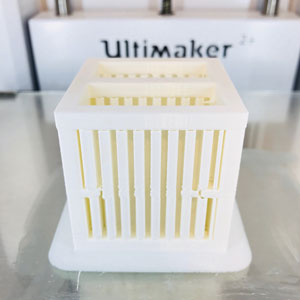 Printing inner structure
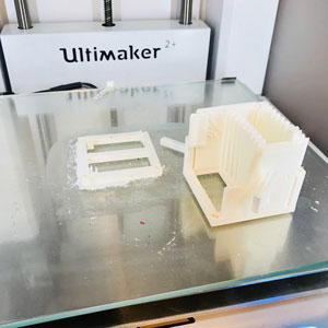 Inner structure broke when taking it out
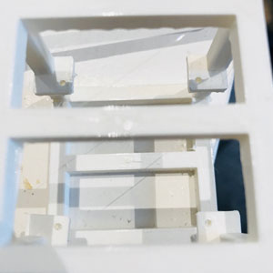 Holes for LED too small, holes for board, small but ok
Design and make the cube
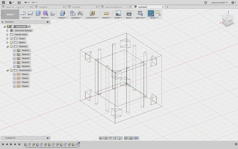 The cube in Fusion 360 to be cut in cardboard
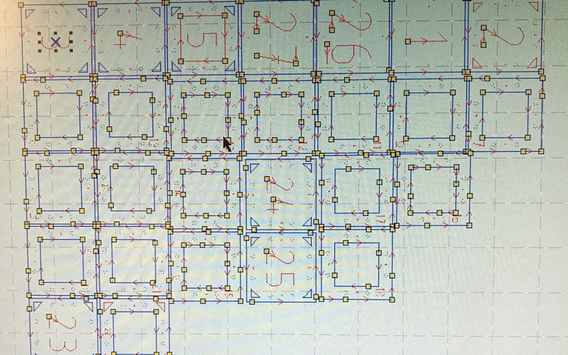 Sliced pieces to bu cut in laser cutter
Testing magnets
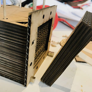 Cube opens up when magnets attract
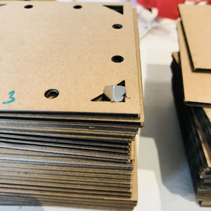 Holes for magnets too small
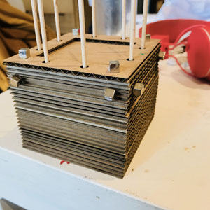 Magnets attract to all sides
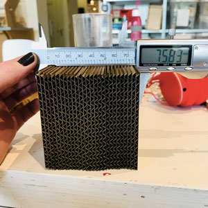 Cube smaller than 80mm
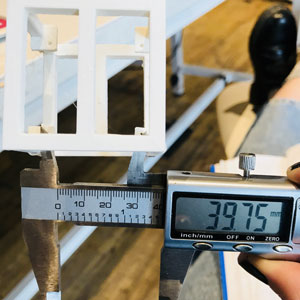 Inside of inner structure is smaller than 40mm
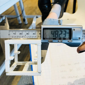 Inner structure smaller than 50mm
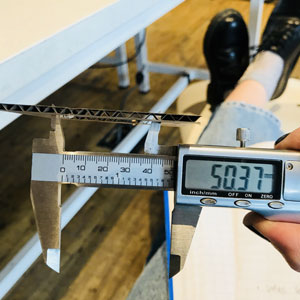 Inside of cube should be big enough
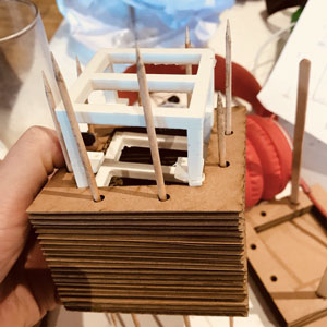 Inner structure do not fit
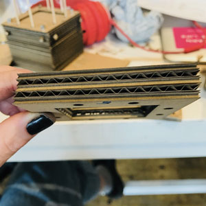 Great way to have LEDs shine through